Each cruise is expensive, so we need instruments deployed in the photic zone to last the full six months without significant fouling. Six weeks into our test, the unprotected oxygen sensor was clearly fouled while the UV protected sensor is still producing reasonable data. We intend to deploy the UV device with all of our upper water column oxygen sensors in the future, and will experiment with the UV light on our other optical instruments."
Jonathan Fram
Assistant Professor, Oregon State University
Challenge
Oregon State University (OSU) operates the Coastal Endurance Array component (located off the coast of Oregon, see Figure 1) of the Ocean Observatories Initiative (OOI). The Coastal Endurance Oregon Shelf Surface Mooring (see Figure 2) is located on the Continental Shelf about 16 km off the Oregon coast. The Endurance Array has the highest primary productivity of OOI’s sites due to coastal upwelling, so Endurance Array instruments in the photic zone face the most biofouling seen by OOI. As operators of this part of OOI, the OSU-OOI team is always looking for ways to mitigate biofouling. To ensure the project would run smoothly, OSU conducted trials in preparation. The team at OSU needed a robust antifouling solution that would overcome two principal challenges:
- Budget limitations: Maintenance cruises are costly. The instrumentation would need to perform for six months at a time without intervention.
- Complex surfaces: The sensing surfaces to be deployed are complex and fragile, ruling out most biofouling control technologies as viable methods. They needed a way to prevent growth without damaging the critical surfaces nor affecting sensor readings.
OOI'S MISSION
OOI's mission is to “deploy a networked infrastructure of science-driven sensor systems to measure the physical, chemical, geological and biological variables in the ocean and seafloor.”
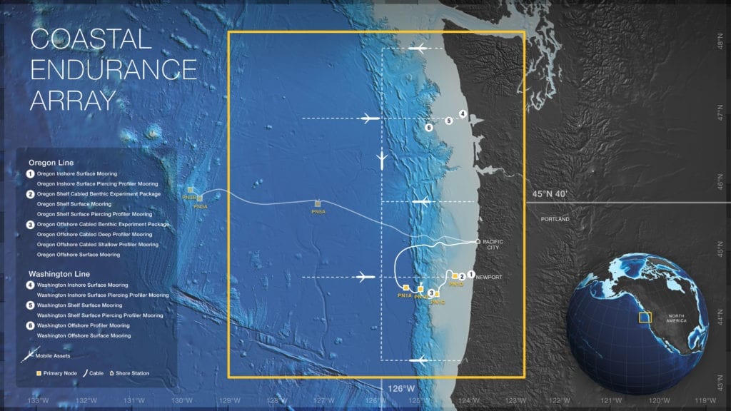
Figure 1: Map of the Coastal Endurance Array. (Image courtesy of Ocean Observatories Initiative)
Solution
Considering the challenges they faced, OSU approached AML Oceanographic to learn more about UV biofouling control technology. They then purchased two Cabled UVs to test. In October 2017, Cabled UV was deployed on one of two Aanderaa Dissolved Oxygen sensors as part of the Instrument Package (see Figure 2). With the aptly named Near Surface Instrument Frame just 7 meters below the surface, biofouling of critical surfaces would develop swiftly if preventative measures were not taken, leading to sensor drift within weeks. Also fit with a Cabled UV was a camera lens deployed to see benthic organisms and sand features on the seafloor. At 3-5 meters away from the lens, the seabed would only be visible if the lens and its lights remained clear of fouling.
WHY ARE DISSOLVED OXYGEN SENSORS IMPORTANT?
Upwelling can introduce hypoxic, low oxygen waters to the environment and harm local organisms, making oxygen sensors a key component of OOI's program.
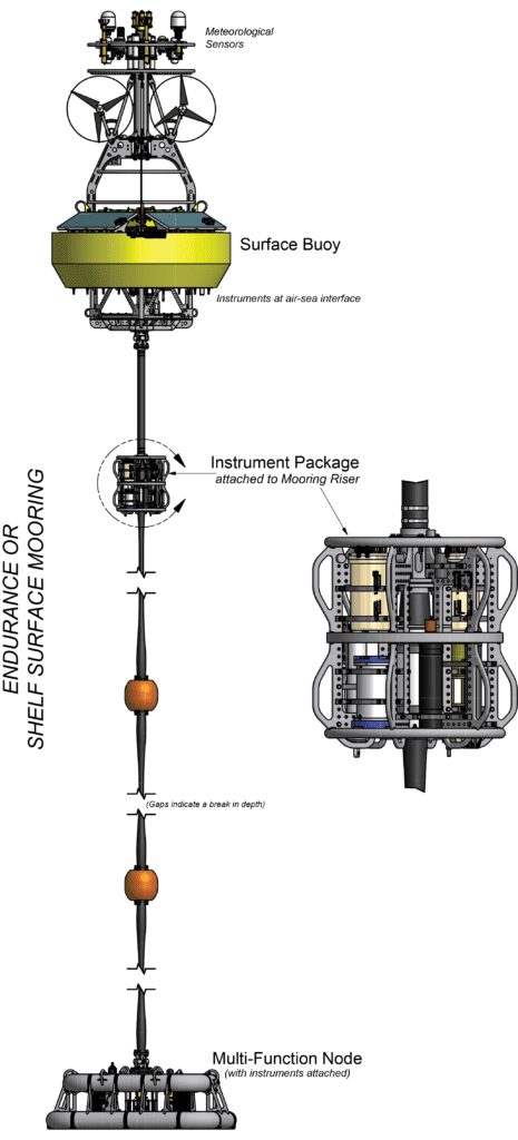
Figure 2: The Coastal Endurance Oregon Shelf Surface Mooring. Cabled UV was deployed on one of two dissolved oxygen sensors as part of the Instrument Package. (Image courtesy of Ocean Observatories Initiative)
Results
In April 2018, the Near Surface Instrument Frame was retrieved for maintenance. It was immediately evident that Cabled UV had kept the dissolved oxygen sensing surface clear of fouling. The reference sensor deployed without protection did not fare so well.
Once back in the lab, it was confirmed that the success was not just cosmetic. The UV-protected dissolved oxygen sensor provided consistent data throughout the six-month deployment (see Figure 3). In contrast, the performance of the reference sensor directly correlated to the level of fouling on the sensing surface. Before the sensor began to foul, the two sensors matched so well that their lines were indistinguishable on the graph. In early December, the unprotected sensor began to stray, with data growing increasingly radical as the fouling reached more advanced stages. A brief respite came in the form of a weather event several months in. With marine growth cleared by strong currents, the reference sensor settled back into step with the protected sensor, only to stray again as the fouling process began anew.
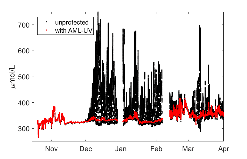
Figure 3: Complete data set for the two oxygen sensors from OSU's test deployment. They were deployed at 7m depth 16 km off the coast of Newport, Oregon. The unprotected reference sensor shows increasingly radical data in in directly correlation with the level of fouling. (Graph courtesy of Oregon State University)
OSU’s UV protected camera lens also fared much better than its unprotected counterpart, which became completely incapacitated due to biofouling over the six month period (see Figure 4).
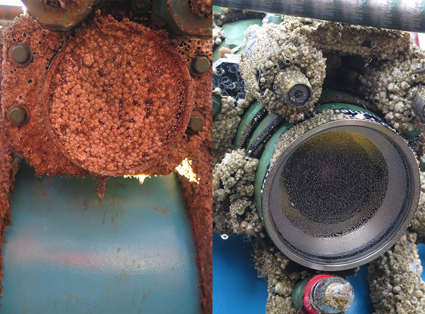
Figure 4: Cameras deployed for six months, without Cabled UV (left), and with Cabled UV (right). Note the incidental protection of the lights above the lens on the camera to the right. (Photos courtesy of Oregon State University)
Following this successful test in which Cabled UV demonstrated its ability to prevent marine growth on OSU’s oxygen sensors and cameras – both fragile and complex surfaces – for six months in-situ, OSU purchased 20 Cabled UV biofouling control systems. Assistant Professor Jonathan Fram explained,
Each cruise is expensive, so we need instruments deployed in the photic zone to last the full six months without significant fouling. Six weeks into our test, the unprotected oxygen sensor was clearly fouled while the UV protected sensor is still producing reasonable data. We intend to deploy the UV device with all of our upper water column oxygen sensors in the future, and will experiment with the UV light on our other optical instruments.
OSU’s trial is the latest in a string of in situ deployments successfully completed using AML’s biofouling control solutions, Cabled UV and UV•XchangeTM.
Learn how UV Biofouling Control can make a difference for you.
Whether it is preventing biofouling-induced drift to keep sensor data accurate, or keeping a camera lens clean to maintain a quality image, our UV antifouling technology optimizes the performance of the instrumentation that it is employed to protect.